Thames Water: Pipeline Condition Assessment at Scale
Building Evidence for Smarter Investment
Thames Water is the largest water and wastewater services provider in the United Kingdom, delivering clean drinking water to over 15 million people across London and the Thames Valley. Its vast underground network includes thousands of kilometers of aging metallic and non-metallic mains, many of which face increasing risk of deterioration due to age, material type, and operating environment. Maintaining this critical network requires robust condition assessment to prioritize renewal investments effectively.
To meet this need, Thames Water partnered with Binnies, a leading engineering and environmental consultancy, and KenWave’s exclusive delivery partner in the UK. Leveraging Binnies’ deep expertise in asset management and KenWave’s patent-pending Dynamic Response Imaging™ (DRI™) solution, Thames Water initiated one of the largest non-invasive pipeline condition assessment programs in the country.
The Challenge
As part of a regulatory requirement, Thames Water was tasked with completing surveys at 1,000 locations across its London distribution system by March 2025. The data gathered would be used to inform a deterioration model designed to guide renewal priorities and justify capital investment. The challenge was not only the scale—covering hundreds of kilometers of buried infrastructure—but also the need for reliable data that could withstand regulatory scrutiny.
The utility needed a solution that could be applied consistently across different pipe diameters, materials, and operating environments without interrupting service to customers. Conventional approaches such as excavations or destructive sampling would have been costly, time-consuming, and disruptive in a dense urban environment. Thames Water required a modern condition assessment approach capable of delivering accurate structural insights quickly, efficiently, and non-invasively.
The Solution
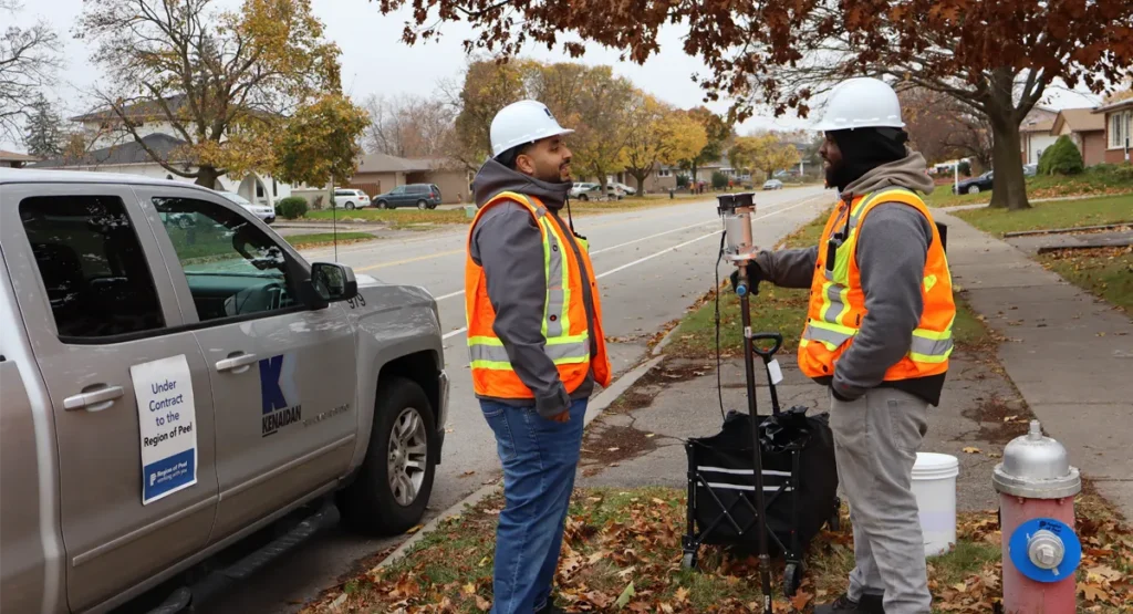
Binnies deployed KenWave’s Dynamic Response Imaging™ (DRI™) solution to meet this need. The program began with an initial set of surveys to establish proof of performance, which underwent independent validation. Based on the accuracy and repeatability of the results, Thames Water awarded Binnies the remaining scope of 733 survey locations. The work demonstrated the value of combining strong engineering oversight with cutting-edge technology.
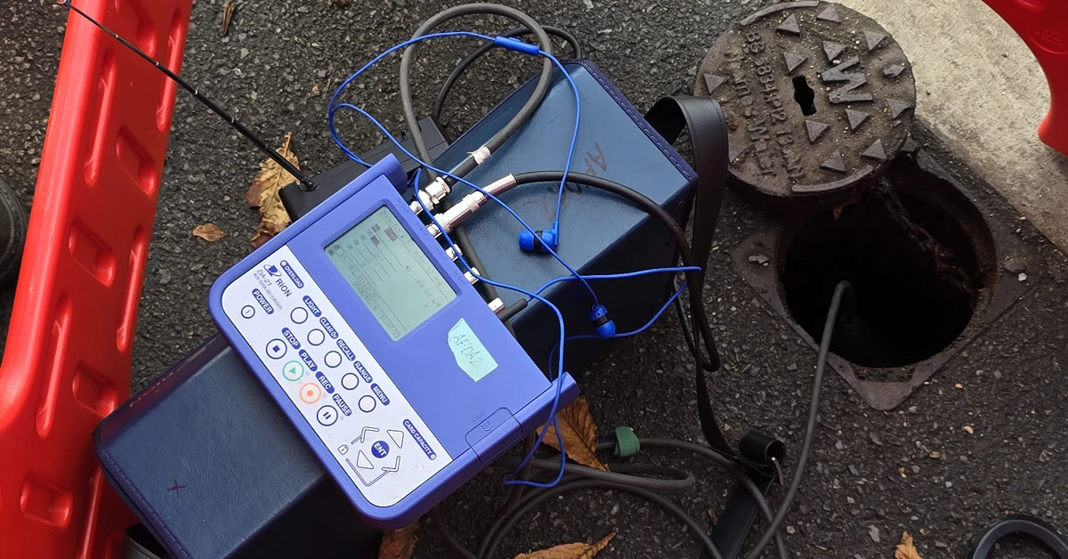
DRI™ introduced controlled vibration signals into the pipeline from existing fittings or small access points. These signals allowed the technology to map pipe wall condition over long distances without excavation or service disruption. Because DRI™ can be applied across all pipe materials and diameters, the entire program was executed using a single survey method. This reduced logistical complexity, avoided enabling works, and provided Thames Water with a consistent dataset across its network.
How Did DRI Perform?
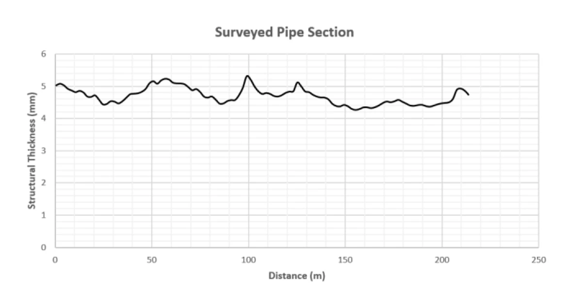
The condition assessment program delivered clear, measurable benefits for Thames Water. Pipe wall thickness was measured with high accuracy and 2-meter resolution along every inspected main, providing the utility with a level of detail previously unattainable through conventional methods. These results gave confidence not only in the data itself but also in the decision-making processes it supported.
By integrating DRI™ survey outputs into its asset management framework, Thames Water was also able to assess the appropriateness of planned £225M mains renewal investment. The insights on asset condition and remaining asset life provided a robust evidence base for future capital planning, that will help the utility direct resources where they are most needed. The program established a foundation for sustainable investment in London’s buried water infrastructure, ensuring long-term reliability for millions of customers while maximizing value for every pound spent.

